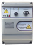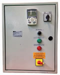
Manual speed control
|
|

Control panels
Control panels with inverter widely
used on board for ccntrol and regulation
of pumps and blowers
|
GENERAL FEATURES
- Supply 3Phs+N+PE 400V±10% 50/60Hz for pump/ventilator “3Phs+PE 400V±10% 50/60Hz” or 1Phs+N+PE 230V±10% 50/60Hz for for pump/ventilator “3Phs+PE 230V±10% 50/60Hz”;
- Selector switch, Thermostatic/off/Inverter pump/ventilator (possibility of emergency operation thermostatic or pressure switch);
- Input signal 4-20 mA from pressure transmitter, termperature transmitter or flowmeter (not included) for Automatic Speed Regulation;
- Inverter in function light;
- Inverter in protection light;
- Frequency converter made of primary brand;
- EMC suppression filter for residential and industrial applications;
- Fuses for inverter & motor protection;
- Auxiliary protection fuses;
- Intelligent keyboard programming in front panel;
- Forced ventilation system for inverter cooling from 4 kW power;
- Free contact alarm relay;
- General blook-door switch;
- Steel box;
- Cable glands with stress relief;
- Terminal board;
- User manual;
- Electric Drawing and CE Declaration;
- Degree of protection IP54.
For distance over 50 meters please contact C.E.M srl
Control panels for pumps and double water pressure systems
Control panel working modes (with pressure sensor)
SINGLE PROBE MODE
In the single probe setting the system keep the value from a single pressure sensor, compare this result with a setpoint value (for instance 2 bar), and if this value is lower than setpoint (which is the minimum acceptable value) will change the pump’s speed to bring the value above the setpoint. Once the value has stabilized above the setpoint, 2 options are available:
1) The pump still running at minimum speed
2) Switch off the pump (energy saving) after a time that can be set and switch it on again only if the pressure lowers below to setpoint value
Control panels for blowers
Control panel working modes (with temperature sensor)
DIFFERENTIAL MODE
In the differential setting, the system will check the Tamb*-Text** difference, compare the result with a setpoint value (for instance 10°C) and will modulate the fan (in case the temperature delta exceeds the setpoint) in order to bring the delta T to a value below the setpoint (which in the maximum value allowed). Obviously, as this is a differential temperature, the system will work by subtraction, i.e. 45°C-35°C produces the same result as 55°C-45°C. Once the differential value has stabilized below the setpoint, 2 options are available:
1) The fan still work at minimum speed,
2) Switch off the fan (energy saving) after a time that can be set and switch it on again only if the delta T exceeds the setpoint again.
* Tamb: internal temperature (ex. engine room)
**Text: external temperature
On request are available 2 separate digital input:
- ENGINE ENABLING: the fan will start and regulated with differential Temperature (through internal & external temperature senson Tamb-Text). When the engine is swich off the ventilators should continue running or in costant temperature mode, until the engine room has cooled down at the delta T (or setpoint). If “delta T” is negative ( external temperature higher then internal temperature) the fan won’t start automatically ( the user should use manual enabling).
- MANUAL ENABLING: the fan will start and forced to work at the set speed (for instance 50% of maximum speed, anyway it should be regulated). When the contact is open, the fan will be stopped.